CircuitPython on an old ESP32
Recently I got an e-Ink display which I wanted to test with CircuitPython. Since I have some classic ESP32 devkits lying around, I wanted to use one of these.
In this post I will show how I flashed the microcontroller and how I installed scripts, Python modules and other resources to the ESP32 using a serial connection and Wi-Fi.
What is the challenge with classic ESP32s? Modern microcontrollers like the Raspberry Pi Pico
(RP2040) expose a CIRCUITPY filesystem over USB mass storage (MSC), so they behave like a USB
stick. Older boards such as the classic ESP32 (ESP-WROOM-32) lack this feature, which makes
copying files to and from the device a bit harder.
Install CircuitPython
First things first. We start by downloading a CircuitPython image from the circuitpython.org downloads. I went for the DOIT ESP32 Devkit Image. If you have a modern browser you can also use the web based installer (requires web serial) to directly flash the microcontroller, otherwise use esptool for the job:
$ uvx esptool write-flash -z 0x0 adafruit-circuitpython-doit_esp32_devkit_v1-en_US-10.2.0.bin
esptool v5.2.0
Connected to ESP32 on /dev/ttyUSB0:
Chip type:          ESP32-D0WDQ6 (revision v1.0)
Features:           Wi-Fi, BT, Dual Core + LP Core, 240MHz, Vref calibration in eFuse, Coding Scheme None
Crystal frequency:  40MHz
MAC:                cc:50:e3:80:ad:50

Stub flasher running.

Configuring flash size...
Flash will be erased from 0x00000000 to 0x001aafff...
Compressed 1745408 bytes to 1161491...
Writing at 0x0006f8ec [=====>                        ]  22.6% 262144/1161491 bytes...
(uvx comes with uv and makes it easy to run Python scripts,
comparable to what npx does for JavaScript).
Connect and test CircuitPython
We open a serial connection to the microcontroller and use a REPL1 to interact with the Python interpreter:
$ screen /dev/ttyUSB0 115200    # use screen command as a serial terminal
Adafruit CircuitPython 10.2.0 on 2026-04-22; ESP32 Devkit V1 with ESP32
>>> import os
>>> os.uname()
(sysname='ESP32', nodename='ESP32', release='10.2.0', version='10.2.0 on 2026-04-22', machine='ESP32 Devkit V1 with ESP32')
Now CircuitPython is installed and ready to be used. Time to set up the display.
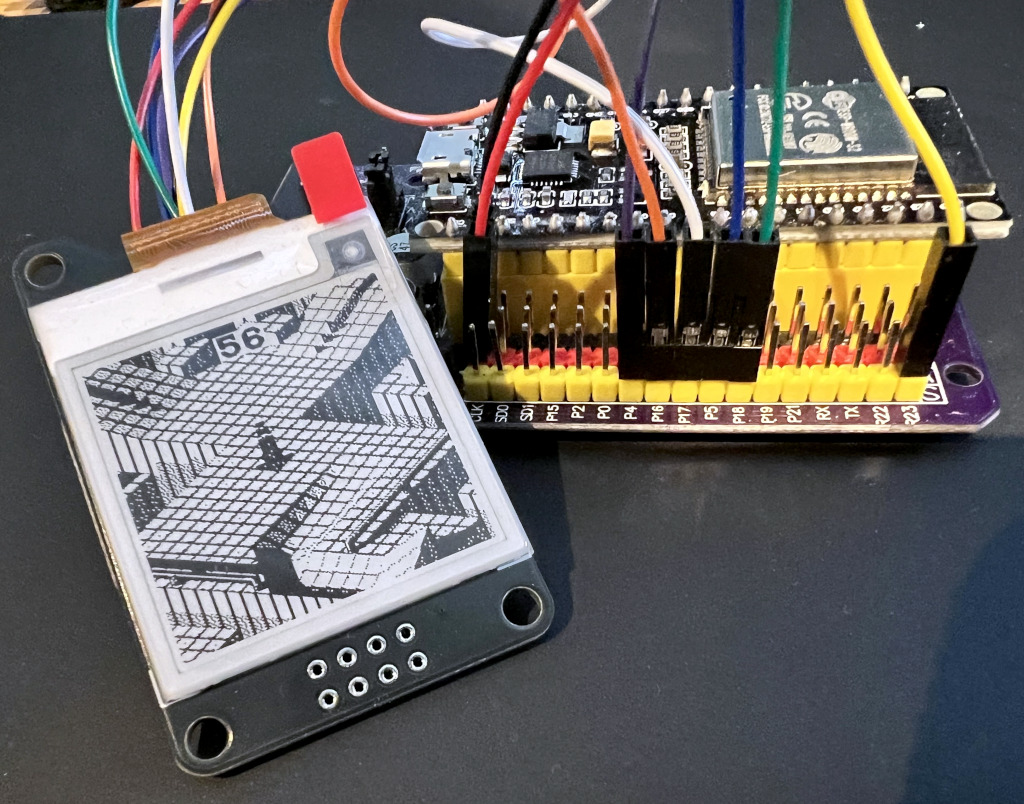
Connect the e-Ink display to the ESP32
The e-Ink display I use here is a WeAct Studio 1.54" monochrome display, which is compatible with
comparable Waveshare models. Like these, it is driven by an SSD1681 controller. Connecting the
e-Ink display to the ESP32 is straightforward. Take care to connect the wires correctly, especially
if your ESP32 board differs. The wiring scheme used here assumes the display uses 4-wire
SPI and is connected as follows:
| Signal | GPIO | Function |
|---|---|---|
BUSY | 4 | Busy Status Output |
CS | 5 | SPI Chip Select |
RES | 16 | Reset |
D/C | 17 | SPI Data/Command Select |
SCK | 18 | SPI Serial Clock |
MOSI | 23 | SPI Master Out / Slave In |

The app
The app to drive the e-Ink display is very simple. We just initialize the display, load the image, which is stored as a BMP file, and send the image to the display. The full script is below. It is based on official Adafruit examples:
# CircuitPython example: load an image the show it on an e-Ink display
def main():
    # Wrap everything in main() so locals are freed on return
    import time
    import board
    import displayio
    import fourwire
    import adafruit_ssd1681

    displayio.release_displays()

    spi = board.SPI()  # Uses SCK(D18) and MOSI(D23)
    epd_cs = board.D5
    epd_dc = board.D17
    epd_reset = board.D16
    epd_busy = board.D4

    display_bus = fourwire.FourWire(
        spi, command=epd_dc, chip_select=epd_cs, reset=epd_reset, baudrate=1000000
    )
    time.sleep(1)

    display = adafruit_ssd1681.SSD1681(
        display_bus, width=200, height=200, busy_pin=epd_busy, rotation=180
    )

    g = displayio.Group()

    pic = displayio.OnDiskBitmap("/mm.bmp")
    t = displayio.TileGrid(pic, pixel_shader=pic.pixel_shader)
    g.append(t)

    display.root_group = g

    display.refresh()


main()
Install the app on the ESP32
To get our files to and from the device, we have two options:
- transfer files over the serial connection, or
- transfer files over Wi-Fi using the so-called web workflow, which must be set up before
Installing over the serial connection with ampy
We use ampy to copy all files to the microcontroller
manually over the serial connection. ampy is a simple command line tool to interact with a
MicroPython or CircuitPython board over a serial connection.
Preparing the library files
First we need to obtain the
adafruit_ssd1681 module to drive the
e-Ink display. It is included in a compiled bytecode version (.mpy extension) in the official
Adafruit CircuitPython bundle. Since the ESP32 does not
support USB storage, we need to obtain and install the library manually. Luckily we can use the
circup tool, as we would on a microcontroller
supporting USB storage. If necessary, circup also downloads dependencies. By passing the --path,
--cpy-version (must match the CircuitPython version flashed on the target device) and
--board-id options, circup installs the files locally, instead of trying to install it on a
device:
$ mkdir -p fakedevice
$ uvx circup --path fakedevice/ --cpy-version 10.2.0 --board-id unused install adafruit_ssd1681
Found device unused at fakedevice/, running CircuitPython 10.2.0.
Using latest bundle for adafruit/CircuitPython_Community_Bundle (20260414).
Downloading 'py' bundle for adafruit/Adafruit_CircuitPython_Bundle (20260508).py:
Extracting:  [####################################]  100%

OK

Downloading '10mpy' bundle for adafruit/Adafruit_CircuitPython_Bundle (20260508).10.x-mpy:
Extracting:  [####################################]  100%

OK

Using latest bundle for adafruit/Adafruit_CircuitPython_Bundle (20260508).
Searching for dependencies for: ['adafruit_ssd1681']
Ready to install: ['adafruit_ssd1681']

Installed 'adafruit_ssd1681'.
$ ls -l fakedevice/lib/
.rw-r--r--@ 862 jd  14 May 16:55 adafruit_ssd1681.mpy
The SSD1681 library is now downloaded to fakedevice/lib and ready to be copied to the device.
Transfer files over the serial connection
For our demo app, we need to transfer the following files:
code.py- our actual Python script, that gets automatically executed after bootmm.bmp- the image we want to show on the e-Ink display (converted with Image Magick2)adafruit_ssd1681.mpy- the Adafruit driver for theSSD1681based e-Ink display that we previously downloaded.
We assume that the ESP32 is connected to /dev/ttyUSB0 and use ampy to copy the files:
$ uvx --from adafruit-ampy ampy --port /dev/ttyUSB0 put code.py /code.py
$ uvx --from adafruit-ampy ampy --port /dev/ttyUSB0 put mm.bmp /mm.bmp
$ uvx --from adafruit-ampy ampy --port /dev/ttyUSB0 put fakedevice/lib/adafruit_ssd1681.mpy /lib/adafruit_ssd1681.mpy
Checking the device state with ampy ls we see all files arrived as expected:
$ uvx --from adafruit-ampy ampy --port /dev/ttyUSB0 ls
/boot_out.txt
/code.py
/lib
/mm.bmp
/sd
$ uvx --from adafruit-ampy ampy --port /dev/ttyUSB0 ls lib
/lib/adafruit_ssd1681.mpy
After resetting the device, CircuitPython runs code.py on boot, and the e-Ink display will show
our test image (assuming everything was wired up correctly).
Installing the app using web workflow (Wi-Fi)
Since the ESP32 provides Wi-Fi, we can also use a Wi-Fi connection to transfer the files to the
device. This doesn’t require a connection to your PC and allows us to directly use circup for
dependency management. To do so, we need to enable the Adafruit web
workflow
by providing a settings.toml file and then restarting the device. On success, a web server on port
80 should now be running on the device. It is accessible either by IP address or by
mDNS name (by default circuitpython.local).
Create a file settings.toml with your Wi-Fi configuration, e.g.
CIRCUITPY_WIFI_SSID = "mywifi"
CIRCUITPY_WIFI_PASSWORD = "mysecret"
CIRCUITPY_WEB_API_PASSWORD = "passw0rd"
Copy settings.toml to the ESP32 (don’t forget to adjust the values to match your setup):
$ uvx --from adafruit-ampy ampy --port /dev/ttyUSB0 put settings.toml /settings.toml
Reset and test the web workflow with:
$ curl -L http://circuitpython.local/cp/version.json
{"web_api_version": 4, "version": "10.2.0", "build_date": "2026-04-22",
 "board_name": "ESP32 Devkit V1", "mcu_name": "ESP32", "board_id": "doit_esp32_devkit_v1",
 "creator_id": 2966421504, "creation_id": 3276802, "hostname": "cpy-sp32_devkit_v1-cc50e380ad50",
 "port": 80, "UID": "CC053E08DA05", "ip": "192.168.200.158"}
If mDNS does not work, we can connect to the device directly to find out its IP address:
$ screen /dev/ttyUSB0 115200
>>> import wifi
>>> wifi.radio.ipv4_address
192.168.200.158
<CTRL>-A + K
[screen is terminating]
Beyond the raw File REST API,
the next sections walk through the browser-based Adafruit Web Code Editor, a custom mDNS name,
and the two command line wrappers circup and cpremote.
Using the Adafruit Web Code Editor
If the web workflow is running on the device, we can use the Adafruit Web Code Editor to start hacking the device. Just open http://circuitpython.local/code/ in your browser to start the IDE, giving you easy access to the files and other functionalities.


Setting a custom mDNS name for the device
Setting an mDNS name for our device allows us to access it by name, without knowing its IP address.
A simple way to change the mDNS name is to read a value from settings.toml and pass it
to CircuitPython’s mdns server. We do that early in the boot process by providing a custom
boot.py file:
# set a custom mDNS and hostname (set in settings.toml as HOSTNAME)
import os

name = os.getenv("HOSTNAME")
if name:
    import wifi
    import mdns
    mdns_server = mdns.Server(wifi.radio)
    mdns_server.hostname = name
    wifi.radio.hostname = name
Add HOSTNAME = "myesp32" to settings.toml alongside the Wi-Fi credentials, then reset the
device. It is now reachable as myesp32.local on the local network. The remaining examples use
myesp32.local; if you skipped this step, substitute circuitpython.local.
Install dependencies with circup
Now that we have the web workflow up and running, we can directly use circup to install
the dependencies on the microcontroller:
$ export CIRCUP_WEBWORKFLOW_PASSWORD="passw0rd"
$ uvx circup --host myesp32.local install adafruit_ssd1681
Found device doit_esp32_devkit_v1 at http://:passw0rd@myesp32.local:80, running CircuitPython 10.2.0.
Using latest bundle for adafruit/CircuitPython_Community_Bundle (20260414).
Using latest bundle for adafruit/Adafruit_CircuitPython_Bundle (20260507).
Searching for dependencies for: ['adafruit_ssd1681']
Ready to install: ['adafruit_ssd1681']

Installed 'adafruit_ssd1681'.
Using the cpremote tool to transfer files
If we want to stay on the command line, we can use cpremote and the web workflow to transfer files to and from the device, e.g.:
$ export CPREMOTE_PASSWORD=passw0rd
$ export CPREMOTE_HOST=http://myesp32.local
$ uvx cpremote ls
Host http://myesp32.local, directory /
Size    Modified        Name
        Jan 01  2000    sd/
159     May 07 17:51    settings.toml
958     Jan 01  2000    code.py
        Jan 01  2000    lib/
162     Jan 01  2000    boot_out.txt
5662    Jan 01  2000    mm.bmp
248     May 07 17:51    boot.py
free: 2369 None, total: 2391 None, block size: 512, writable: True
$ uvx cpremote put code.py
File existed and overwritten
Tool review
Regarding tooling, the ESP-WROOM-32 is a second-class citizen in the CircuitPython ecosystem. No single command line tool fully covers file management over either the serial connection or the web workflow.
One tool worth mentioning up front is the Thonny IDE. It also works with CircuitPython over a serial connection and lets you get, put, and list files on the device, as well as run a remote REPL. Configure it with the “CircuitPython (generic)” interpreter.

This table shows the compatibility of the various tools (according to my tests) with CircuitPython 10.2 and current tool versions3 at the time of writing:
| Feature | ampy | cpremote | circup | mpremote | curl | Web Code Editor | Thonny |
|---|---|---|---|---|---|---|---|
| type | CLI | CLI | CLI | CLI | CLI | Web based UI | Desktop IDE |
| tool maintained | No | Yes | Yes | Yes | Yes | Yes | Yes |
CIRCUITPY drive | No | No | Yes | No | No | No | Yes |
| serial connection | Yes | No | No | Yes | No | No | Yes |
| web workflow | No | Yes | Yes | No | Yes | Yes | No |
| get files | No | Yes | No | Yes with cat command | Yes | Yes | Yes |
| put files | Yes | Yes | No | No | Yes | Yes | Yes |
| ls files | Yes | Yes | No | No | Yes (via /fs/) | Yes | Yes |
| dep management | No | No | Yes | No | No | No | No |
Unfortunately I have also added cpremote does not transfer binary files to the device (e.g. our mm.bmp test image;
i have filed an issue), socurl
as an option. To upload the binary mm.bmp test image, use e.g. curl -u :passw0rd -X PUT --data-binary @mm.bmp -L --location-trusted http://circuitpython.local/fs/mm.bmp. We pass
--location-trusted so the basic-auth credentials survive the redirect to the device’s IP, which is
fine on a trusted home network but worth knowing before reusing the command elsewhere.
Troubleshooting
Some general tips for troubleshooting:
- proceed step-by-step. Use the REPL to test if necessary.
- make sure you flashed a firmware image that is compatible with your board.
- double-check the wiring of the display. Depending on your board and display, details may vary.
- the serial device
/dev/ttyUSB0may change if you reconnect the board to your computer. Checkls /dev/ttyUSB*to find out the current serial device. - use
avahi-browse -rt _circuitpython._tcp --parsableto discover devices advertising the CircuitPython web workflow over mDNS. - check
boot_out.txton the device after a reset. CircuitPython writes the firmware version and any boot-time errors there. - on Linux, make sure your user is in the group owning
/dev/ttyUSB*(typicallydialouton Debian/Ubuntu,uucpon Arch,dialouton Fedora). Otherwisescreenandampywill fail with a permission error. - if the REPL is unresponsive, press
Ctrl-Cto interrupt the running script, thenCtrl-Dto trigger a soft reboot without unplugging the device. .mpyfiles are versioned and must match the CircuitPython major version on the device. If you seeImportError: incompatible .mpy fileafter an upgrade, redownload the library bundle.
Summary
CircuitPython is perfectly usable, even when no USB MSC mode is available, like on an older
ESP-WROOM-32 model. After flashing the firmware with a browser or esptool we can already talk to
the board over a serial REPL.
Tooling over the serial link is patchy and forces us to mix and match existing tools to reach
our goals. The more productive path is to copy a settings.toml with a Wi-Fi configuration to
the microcontroller, which enables the web workflow. That unlocks Adafruit’s Web Code Editor for
interactive browser-based programming, and command line tools like cpremote (with limitations)
and circup to manage files and dependencies on the device.
References
- esptool - tool to flash Espressif SoC (e.g. ESP32)
- cpremote - an unofficial command line tool for interacting with a CircuitPython remote filesystem using the web based workflow
- adafruit-ampy - Utility to interact with a CircuitPython or MicroPython board over a serial connection
- circup - an Adafruit tool to manage and update libraries (modules) on a CircuitPython device
- CircuitPython Library bundles - bundle with all current libraries available for CircuitPython
- mpremote - MicroPython’s tool to interact with a MicroPython device over a serial connection
- Thonny - Python IDE for beginners
- CircuitPython cheat sheet
REPL - (interactive) Read-Eval-Print Loop ↩︎
I used this command to convert the screenshot to a monochrome, dithered BMP image:
↩︎$ magick original.png -unsharp 0x1 -gravity north -crop 200x200+0+0 +repage \ -colorspace Gray \ -blur 0x0.3 -dither FloydSteinberg -colors 2 \ -type bilevel BMP3:output.bmpVersions used: mpremote=1.28.0, ampy=1.1.0, circup=3.0.1, cpremote>1.0.3 (tested commit 2d47f29), thonny=5.0.0 ↩︎